We continue the series of blog posts on how to create popular types of diagrams available in the DHTMLX Diagram library. This time, we will provide you with a detailed guide on how to build a JavaScript network diagram using our diagramming component. Equip yourself with a DHTMLX Diagram trial version and follow the instructions below.
What is a network diagram
A network diagram is a type of diagram that helps to visualize the architecture of computer or telecommunication systems of any complexity level (from basic home networks to complex MAN networks or cloud-based storage systems). It depicts various components such as routers, servers, hubs, etc. that shape into a network using special symbols and explains relationships between them.
Network diagrams differ in two main aspects: network type and network topology, or the positioning of their elements.
Network diagrams are commonly divided into two main types:
- Physical network diagrams that represent the physical layout of the network.
- Logical network diagrams that depict how data is transmitted via the network.
When talking about possible arrangement variations for network diagrams, we can point out the following topology options:
- Bus topology
- Star topology
- Ring topology
- Mesh topology
Network diagrams are extensively used in network architecture design. For example, this type of diagram can be helpful in planning the arrangement of networks, determining updates for existing networks or eliminating redundancies, detecting bottlenecks and vulnerabilities, or can be used as a part of network documentation.
Moreover, network diagrams have also gained popularity in project management. Utilizing this type of diagram, project managers can vividly present the workflow of different project activities, monitor the project progress, perform time estimates for the project, and much more.
Example of a JavaScript network diagram by DHTMLX
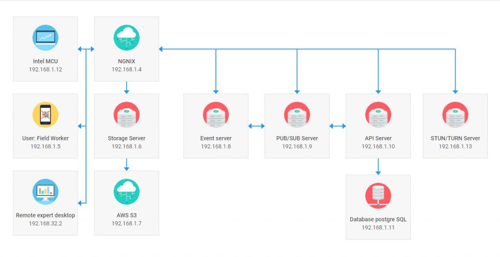
Let us consider the example of a JavaScript network diagram built with the use of the DHTMLX Diagram library.
The example above depicts the architecture of the remote presence software system. This technology creates a virtual presence of a remote expert to consult specialists in any location.
This system includes four main components:
- signal server that provides proper signal transmission (video and audio)
- client-side app on a device
- web UI on a PC for an expert
- process management system/storage/wiki-systems, etc.
How to create a JavaScript network diagram with DHTMLX
Now let us proceed with concrete steps for creating a JavaScript network diagram utilizing our Diagramming component.
1. Initializing DHTMLX Diagram library:
<html>
<head>
<script type="text/javascript" src="codebase/diagram.js"></script>
<link rel="stylesheet" href="codebase/diagram.css">
</head>
<body>
<div id="diagram"></div>
<script>
const diagram = new dhx.Diagram("diagram", {
lineGap: 20
});
</script>
</body>
</html>
First of all, it is necessary to add JS and CSS source files and a container, where your diagram will be placed. The next move is to apply the dhx.Diagram constructor that will help to perform the initialization of your diagram. This function takes two parameters: container originated at the previous step and object with configuration properties.
2. Specifying the default configuration of shapes via the defaults config:
width: 160,
height: 160,
img: "../common/img/network_image/desktop.svg",
text: "Network Card",
ip: "138.68.41.78",
preview: {
scale: 0.8
}
};
When it comes to setting up the configuration properties of shapes for your JavaScript network diagram, you can do it much faster and easier using the defaults config. Our example includes eleven shapes with a similar size (160×160). Each shape has a text naming a particular component of the network, image, and string of numbers for its IP address.
3. Creating a template for custom shapes of the network diagram:
<section class='template'>
<img src='${config.img}' alt='${config.text}'></img>
<span>${config.text}</span>
<span>${config.ip}</span>
</section>
`);
Then, you have to create a new HTML template to make custom shapes for your diagram. In this example, we employ the ES6+ format (ES5 is applicable as well) to set up the template for your custom shapes. By putting to use the template, you can define all necessary content for the shape: an image that shows a specific component of the diagram and alt attribute that provides an alternate text for an image (if the image cannot be displayed), name of the component, and its IP address.
4. Adding shapes to the JS network diagram:
template,
defaults,
});
The next move is to add custom shapes to the diagram. For this purpose, we utilize the addShape method. This method serves to promptly add different shapes generated by employing the templates.
5. Preparing and parsing data into the diagram:
const data = [
{
"id": 1,
"type": "networkCard",
"x": 0,
"y": 380,
"img": "https://docs.dhtmlx.com/diagram/samples/common/img/network_image/desktop.svg",
"text": "Remote expert desktop",
"ip": "192.168.32.2"
},
{
"id": 2,
"type": "networkCard",
"x": 200,
"y": 0,
"img": "https://docs.dhtmlx.com/diagram/samples/common/img/network_image/cloud.svg",
"text": "NGNIX",
"ip": "192.168.1.4"
},
{
"id": 3,
"type": "networkCard",
"x": 0,
"y": 190,
"img": "https://docs.dhtmlx.com/diagram/samples/common/img/network_image/fieldWorker.svg",
"text": "User: Field Worker",
"ip": "192.168.1.5"
},
{
"id": 4,
"type": "networkCard",
"x": 200,
"y": 190,
"img": "https://docs.dhtmlx.com/diagram/samples/common/img/network_image/server.svg",
"text": "Storage Server",
"ip": "192.168.1.6"
},
{
"id": 5,
"type": "networkCard",
"x": 420,
"y": 190,
"img": "https://docs.dhtmlx.com/diagram/samples/common/img/network_image/server.svg",
"text": "Event server",
"ip": "192.168.1.8"
},
{
"id": 6,
"type": "networkCard",
"x": 620,
"y": 190,
"img": "https://docs.dhtmlx.com/diagram/samples/common/img/network_image/server.svg",
"text": "PUB/SUB Server",
"ip": "192.168.1.9"
},
{
"id": 7,
"type": "networkCard",
"x": 820,
"y": 190,
"img": "https://docs.dhtmlx.com/diagram/samples/common/img/network_image/server.svg",
"text": "API Server",
"ip": "192.168.1.10"
},
{
"id": 8,
"type": "networkCard",
"x": 1010,
"y": 190,
"img": "https://docs.dhtmlx.com/diagram/samples/common/img/network_image/server.svg",
"text": "STUN/TURN Server",
"ip": "192.168.1.13"
},
{
"id": 9,
"type": "networkCard",
"x": 200,
"y": 380,
"img": "https://docs.dhtmlx.com/diagram/samples/common/img/network_image/cloud.svg",
"text": "AWS S3",
"ip": "192.168.1.7"
},
{
"id": 10,
"type": "networkCard",
"x": 820,
"y": 390,
"img": "https://docs.dhtmlx.com/diagram/samples/common/img/network_image/database.svg",
"text": "Database postgre SQL",
"ip": "192.168.1.11"
},
{
"id": 11,
"type": "networkCard",
"x": 0,
"y": 0,
"img": "https://docs.dhtmlx.com/diagram/samples/common/img/network_image/core.svg",
"text": "Intel MCU",
"ip": "192.168.1.12"
},
{
"id": "12",
"type": "line",
"from": 4,
"to": 9,
"fromSide": "bottom",
"toSide": "top",
},
{
"id": "13",
"type": "line",
"from": 5,
"to": 6,
"fromSide": "right",
"toSide": "left",
"backArrow": "filled",
},
{
"id": "14",
"type": "line",
"from": 6,
"to": 7,
"fromSide": "right",
"toSide": "left",
"backArrow": "filled",
},
{
"id": "15",
"type": "line",
"from": 2,
"to": 5,
"fromSide": "right",
"toSide": "top",
"backArrow": "filled",
},
{
"id": "16",
"type": "line",
"from": 2,
"to": 8,
"fromSide": "right",
"toSide": "top",
"backArrow": "filled",
},
{
"id": "17",
"type": "line",
"from": 3,
"to": 2,
"fromSide": "right",
"toSide": "left",
"backArrow": "filled",
},
{
"id": "18",
"type": "line",
"from": 2,
"to": 4,
"fromSide": "bottom",
"toSide": "top",
},
{
"id": "19",
"type": "line",
"from": 2,
"to": 7,
"fromSide": "right",
"toSide": "top",
},
{
"id": "20",
"type": "line",
"from": 2,
"to": 6,
"fromSide": "right",
"toSide": "top",
"backArrow": "filled",
},
{
"id": "21",
"type": "line",
"from": 7,
"to": 10,
"fromSide": "bottom",
"toSide": "top",
},
{
"id": "22",
"type": "line",
"from": 2,
"to": 11,
"fromSide": "left",
"toSide": "right",
},
{
"id": "23",
"type": "line",
"from": 2,
"to": 1,
"fromSide": "left",
"toSide": "right",
}
];
To populate your diagram with prepared data, it is necessary to apply the parse method.
6. Styling specific elements of your network graph:
.template {
display: flex;
align-items: center;
justify-content: center;
flex-direction: column;
background: #F7F7F7;
width: 100%;
height: 100%;
border: 1px solid #DFDFDF;
overflow: hidden;
}
.template span {
font-weight: 300;
line-height: 20px;
overflow: hidden;
text-overflow: ellipsis;
white-space: nowrap;
width: 100%;
text-align: center;
}
.template span:not(:last-child) {
font-weight: 500;
margin-top: 16px;
}
.template img {
width: 64px;
height: 64px;
pointer-events: none;
border-radius: 50%;
}
</style>
As the last step, you can make your diagram more visually appealing by setting up style attributes for its elements by means of CSS. We can specify the color characteristics for the background and border of the shape, align items and textual data, size of the image, and other characteristics of shapes utilized in the network diagram.
That’s how you can quickly build an HTML/JavaScript network diagram using the abilities of our diagramming component. As a bonus, you can also examine a complete sample of this network graph and modify it on the fly via our new DHTMLX code snippet tool.
Conclusion
DHTMLX JavaScript Diagram library makes it possible for web developers to generate JS network diagrams and other popular types of graphs and diagrams for visualizing data of any complexity with minimal coding effort. You can set the default configuration for all shapes using just one property, create various custom shapes, and style all shapes and their elements according to your liking. We encourage you to leverage a 30-day tryout version of our library and test its capabilities in your projects.